


- Browse Categories
-
Energy Storage Series
- EV Chargers
- Ring Main Unit Series
- LBS and Recloser
- High & Low Voltage Complete Series
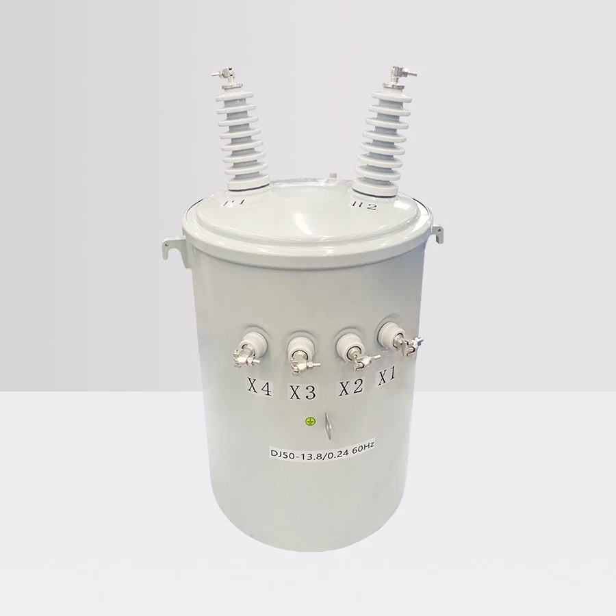
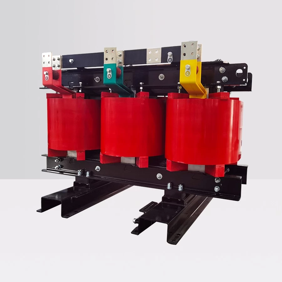
- Distribution Transformers
- Components
- Distribution Automation Terminal Series
- Digital Platform System
- EV Chargers
- Subscribe
-
Get email updates on new products
- Hot Product
- ExhibitionMore>>
-
-
EP 20 concluded, Comking depicted a new vision of the intelligent and sustainable development of the power world
2020 Shanghai International Electric Power Equipment and Technology Exhibition. It has been successfully concluded on December 5~ -
Dry air insulated switchgear debuted at the Asian Power and Electrical Exhibition
From June 6 to 8, 2016, Comking Electric was invited to participate in the 2016 Asian Power and Electrical and Smart Grid Exhibition.
-
- Contact Us
- Please contact our customer care team for customized services.
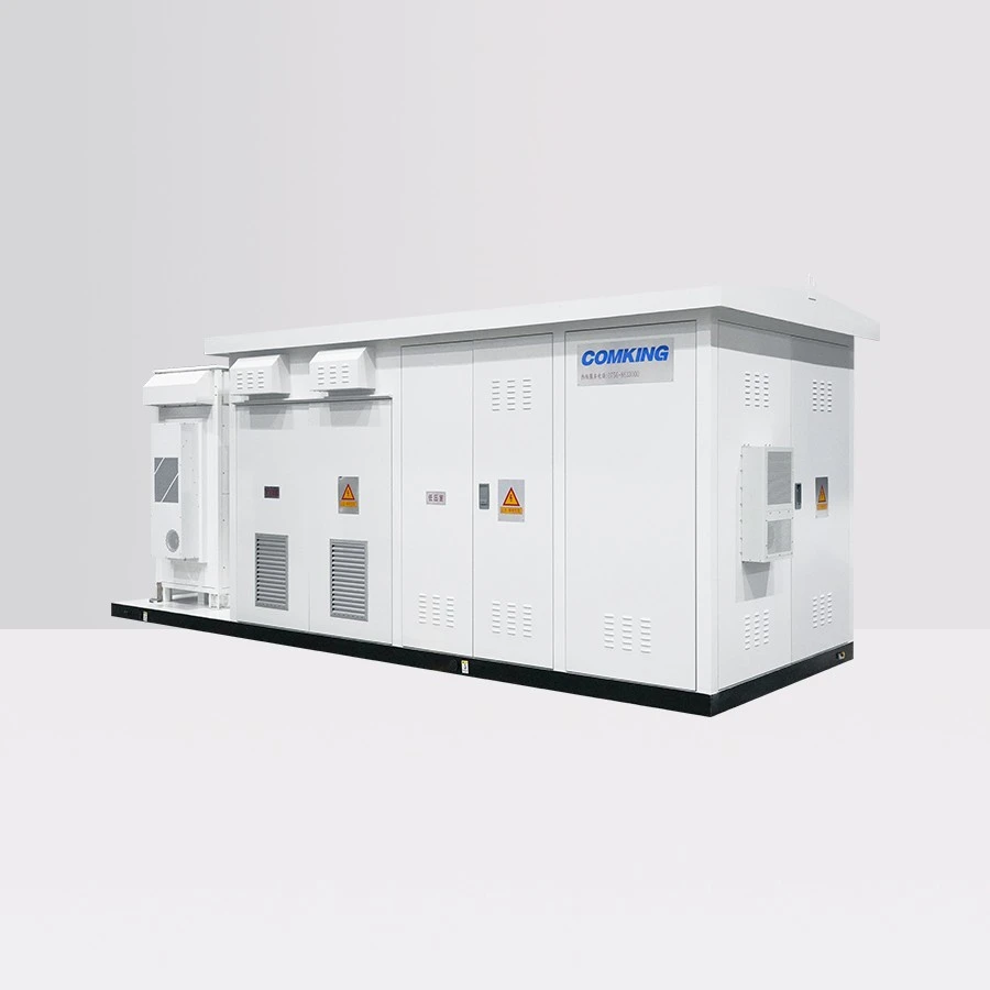
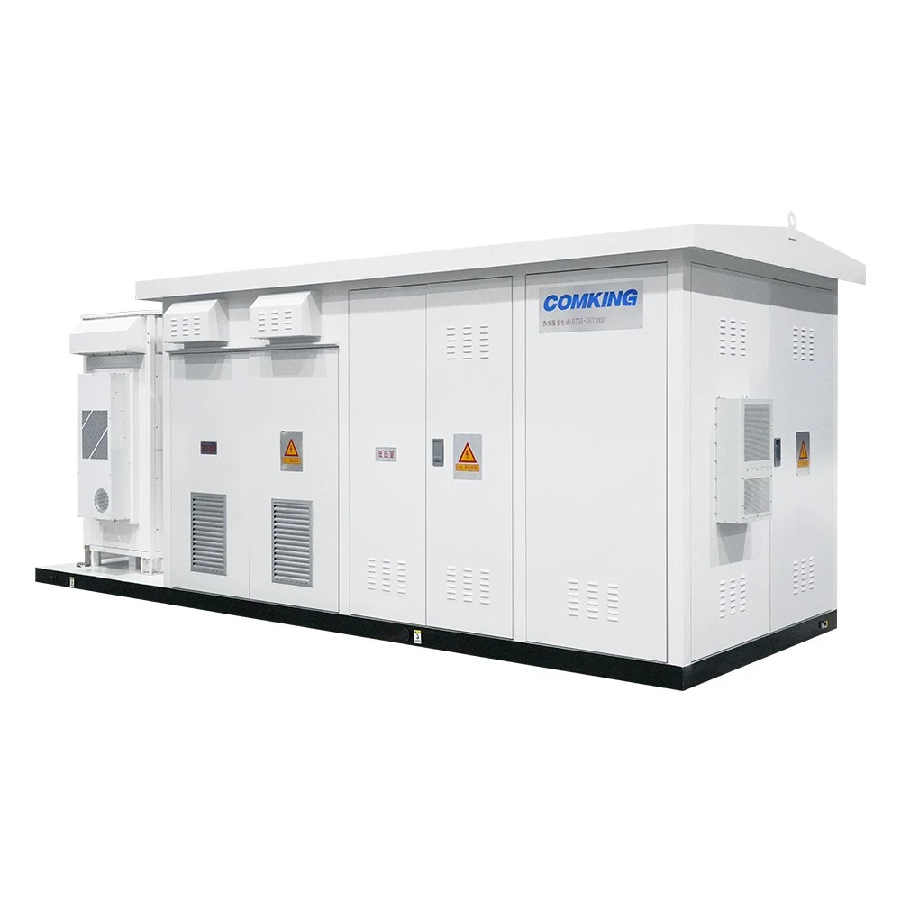
Integrated Power Conversion and Voltage Boosting Cabinet
- The Integrated Power Conversion and Voltage Boosting Cabinet serves as the power unit of energy storage systems. As critical equipment in modern energy conversion and transmission fields, its meticulous design and rational composition are key to achieving efficient and stable operation.
►Overview
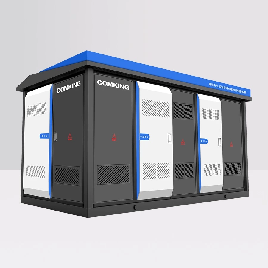
The Integrated Power Conversion and Voltage Boosting Cabinet serves as the power unit of energy storage systems. As critical equipment in modern energy conversion and transmission fields, its meticulous design and rational composition are key to achieving efficient and stable operation. It integrates two essential functions - Power Conversion System (PCS) and voltage boosting transmission - within a compact and efficient cabinet structure. By storing and releasing electrical energy on demand, it balances supply-demand relationships in power systems while enhancing their stability and reliability. Additionally, it enables power balance, improves the sustainability of power systems, reduces peak-valley load differences, and provides vital support for the operation and development of electrical infrastructure.
►Product Composition
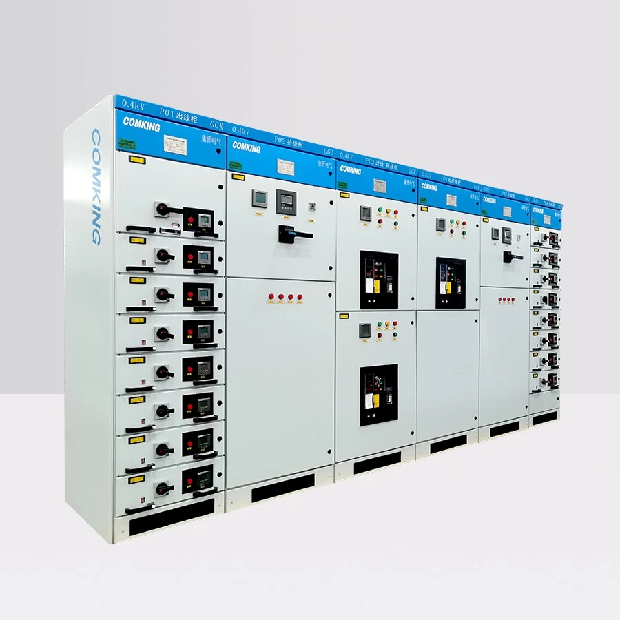
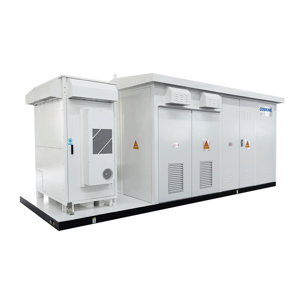
The main components include: a containerized system integrating energy storage converter PCS (mounted on an outdoor skid-mounted base when in skid-mounted configuration), voltage boosting transformer, high-voltage ring main unit, low-voltage distribution cabinet, and other equipment. This design features high integration that reduces on-site construction complexity while offering simplified transportation, installation, operation, and maintenance. Such integrated design delivers numerous significant advantages.
►Product Features
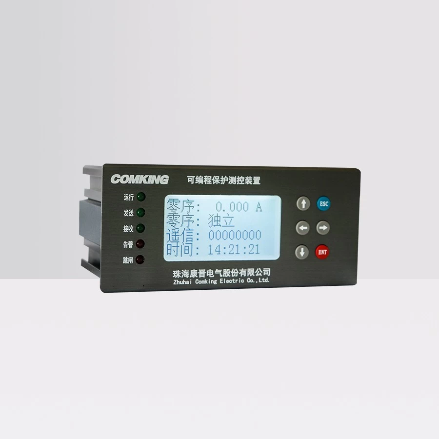
◆ Energy Storage Converter PCS: Installed on the skid-mounted integrated base, this AC/DC conversion device serves as the primary execution unit for controlling battery charging and discharging processes. Composed of a DC/AC bidirectional converter, control unit, and filter circuit. The control unit receives operational commands to manage the converter's charging/discharging operations on the DC battery side while regulating active and reactive power on the AC side.
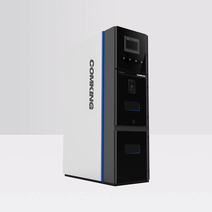
◆ Step-Up Transformer Cabin: The integrated cabin with a built-in transformer is compatible with voltage levels up to 35kV and below, designed to achieve electrical energy step-up functionality. Through the step-up transformer, the energy storage device (PCS) can elevate low-voltage electrical energy to the required high-voltage level, meeting the demand for high-voltage power in long-distance transmission or specific load systems. Simultaneously supports both local and remote monitoring.
◆ The cabin incorporates an emergency lighting system, fire protection system, access control system, and cooling system. Fireproof partitions within the enclosure effectively ensure the normal operation and safety of internal equipment in the integrated step-up cabin.
◆ The integrated design significantly reduces the footprint required for equipment installation. Compared to traditional decentralized inverters and step-up equipment, it consolidates complex circuits and components within a single cabin. This not only minimizes interconnection wiring between devices and reduces line losses but also creates a more compact and aesthetically cohesive system, enabling streamlined layout optimization within limited spaces.
◆ Peak Shaving and Load Leveling: The system enables energy storage and release in response to grid load fluctuations, thereby achieving power system peak shaving. During grid load peaks, the energy storage device can discharge stored electricity to alleviate load pressure. Conversely, during grid load troughs, the device absorbs surplus electricity for storage, preventing system overload and maintaining grid stability.
◆ Grid Stability Enhancement: Enables improvement in grid frequency and voltage stability. When significant fluctuations occur in grid frequency or voltage, the energy storage device can promptly discharge or store energy to maintain grid operation within reasonable parameters.
◆ Emergency Backup Power Supply: When the power system encounters sudden failures or outages, the energy storage device can swiftly switch to emergency backup power mode, providing continuous and stable power supply to critical loads while ensuring operation of essential facilities.
Main Technical Parameters
►Main Technical Parameters
| DC Side Parameters | Maximum DC Bus Voltage | 850V | 1500V | |||||
| Maximum DC Side Current | 1147A*2 | 1147A*4 | 1935A*2 | 1935A*2 | 1935A*2 | 2500A*2/1935A*4 | 1935A*4 | |
| DC Voltage Operating Range | 580V~850V | 1000V~1500V | ||||||
| Number of DC Input Circuits | 2 | 4 | 1/2 | 2 | 2 | 2/4 | 4 | |
| AC Side Parameters | Rated Power | 1000kW | 2500kW | 2500kW | 3150kW | 3450kW | 5000kW | 6250kW |
| Branch Power * Quantity | 500kW*2 | 630kW*4 | 2500kW*1 1250kW*2 |
3150kW*1 | 1725kW*2 | 2500kW*2 1250kW*4 |
1563kW*4 | |
| Maximum Output Power | 1100kW | 2750kW | 2750kW | 3465kW | 3795kW | 5500kW | 6250kW | |
| Isolation Method | Transformer Isolation | |||||||
| Reactive Power Range | 0~1050kvar | 0~2625kvar | 0~2625kvar | 0~3308kvar | 0~3623kvar | 0~5250kvar | 0~6250kvar | |
| Grid-connected Operation Parameters | Rated Grid Voltage | 6kV/10kV/35kV | ||||||
| Rated Grid Frequency | 50Hz/60Hz | |||||||
| Total Current Harmonic Distortion Rate | <3% | |||||||
| Power Factor | -1~1 | |||||||
| Transformer Parameters | Rated Capacity | 1000KVA | 2500KVA | 2500KVA | 3150KVA | 3450KVA | 5000KVA | 6250KVA |
| Transformer Type | Dry-type/Oil-immersed Transformer | |||||||
| LV/MV Voltage | 0.4/(6-35)kV | 0.69/(6-35)kV | ||||||
| No-load Loss | Compliant with National Standards | |||||||
| Load Loss | Compliant with National Standards | |||||||
| No-load Current | Compliant with National Standards | |||||||
| Impedance | Compliant with National Standards | |||||||
| System Parameters | Permitted Ambient Temperature | -30℃ to +60℃ (Derating above 40℃) | -30℃ to +60℃ (Derating above 45℃) | -30℃ to +60℃ (Derating above 50℃) | ||||
| Permitted Relative Humidity | 0~100% | |||||||
| Permitted Altitude | <5000m (Derating above 2000m) | <5000m (Derating above 3000m) | <5000m (Derating above 4000m) | |||||
| Protection Rating | IP54 | |||||||
| BMS Communication Interface | RS485 | |||||||
| EMS Communication Interface | Ethernet | |||||||
| Communication Protocol | Modbus RTU/Modbus TCP/IEC104/IEC61850 | |||||||
| Compliance with Standards | GB/T34120,GB/T34133,GB/T36547 | |||||||
| Grid Support | High/Low Voltage Ride-Through (HVRT/LVRT), Frequency Regulation, Voltage Regulation, Grid-Forming Function, etc. | |||||||
| Overall Dimensions | Depending on Specific Configuration | |||||||
| Weight | Depending on Specific Configuration | |||||||
Click Integrated type Low-voltage integrated distribution box to learn more about the products.
- Other Products

